Bent Plate Settings
- General Overview
- Tips and Tricks
- Related Tools
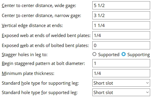
Center to center distance, wide gage: The center-to-center distance from the column of holes on the one bent plate to the column of holes on the other bent plate.
Effect on connection design: The double bent plate connection gage entered here applies when connection design attempts to create wide gage, double bent plate connections. " Wide Gage " is a setting that the user can select when defining a bent plate. For offset framing , connection design may increase this gage.
Center to center distance, narrow gage: The center-to-center distance from the column of holes on the one bent plate to the column of holes on the other bent plate.
Effect on connection design: The double bent plate connection gage entered here applies during Process and Create Solids when connection design attempts to create narrow gage, double bent plate connections. " Narrow Gage " is a setting that the user can select when defining a bent plate. For offset framing , connection design may increase this gage.
Vertical edge distance at ends: The distance from the top (or bottom) edge of the bent plate to the center of the nearest hole.
|
v = vertical edge distance. This distance is measured perpendicular to the slope of the beam when the beam is sloping. |
Exposed web at ends of welded bent plates: The vertical distance from the top (or bottom) edge of the bent plate to the cope on the supported beam.
|
xw = exposed web above a welded bent plate. Connection design welds the bent plate when " Welded " is specified on the Beam Edit window or for an auto standard or user defined connection. |
Effect on connection design: If weld is required across the top of a bent plate, the exposed web must be sufficient to allow this weld.
Exposed web at ends of bolted bent plates: The vertical distance from the top (or bottom) edge of the bent plate to the cope on the supported beam.
|
xw = exposed web above a bolted bent plate. Connection design bolts the bent plate when " Bolted " is specified on the Beam Edit window or for an auto standard or user defined connection. |
Stagger holes in leg to: Supported or Supporting . This applies when bent plates are designed with bolt diameters as large or larger than the diameter you set for Begin staggered pattern at bolt diameter.

If ' Supported ' is selected, connection design staggers the holes on the leg of the bent plate that attaches to the beam on whose edit window the bent plate connection is applied.
If ' Supporting ' is selected, then connection design staggers the holes in the leg of the bent plate that attaches to the supporting member.
Begin staggered pattern at bolt diameter: The minimum bolt diameter at which the bolts are staggered.
Minimum plate thickness: The minimum thickness of designed bent plates.
Effect on connection design: Bent plates are designed to be as thick or thicker than this thickness. The actual designed thickness depends on the design load that the bent plate is subjected to.
To enter gage plate: Type in the ' gage number' followed by ' ga ' (example: ' 4ga ' is rewritten as ' 4GA ' when you Tab out of the field). Right-click tells you the stored thickness (based on industry standards), from which the weight of the gage plate is calculated. Allowable gages are any whole number from 3 to 38 . The " Description " for a gage plate follows the format: ' bent plate prefix ' followed by ' numberGA ' followed by ' x ' followed by ' width ' (example: BPL16GAx15 1/2 ).
Standard hole type for supporting leg: Standard round or Short slot or Long slot or Oversized round or User slot #1 or User slot #2 .

Standard hole type for supported leg: Standard round or Short slot or Long slot or Oversized round or User slot #1 or User slot #2 .


|
|
OK (or the Enter key) closes this screen and applies the settings.
Cancel (or the Esc key) closes this screen without saving any changes.
Reset undoes all changes made to this screen since you first opened it. The screen remains open.
-
Settings applied here are for your current Fabricator . Each Fabricator in your current Job is a different collection of settings. This allows you to change to a different set of Standard Fabricator Connections each time you " Change Fabricator."
- These settings work in coordination with individual beam bent plates "
 Connection specifications " and bent plate configurations to configure connection design for when the Beam Edit window > " Connection type " > " Input connection type " is ' Bent plate ' or ' Auto standard ' or ' User defined '.
- Bent plate input specs (for applying bent plate connections)
- Setup for bent plate connections (index)
- Connection guide (examples of bent plates)

